Monday, September 1, 2014

Finishing the 1st type of retaining wall

In the post last March titled Japanese style retaining walls, I showed prototype photos of two different types of retaining walls I have seen along side the rail lines.  In that post, I also showed the beginnings of the walls I was building from styrene plastic.

For reference, I again show the prototype photo here.  Most of these that I've seen are not quite this bent up.


Recall from that previous post, the wall sections were made from .080 square styrene rod attached to .020 styrene sheet.

When this was fully assembled, it was air brushed with Model Master acrylic aged concrete color.

Then the spaces between the rods were hand painted with a grimy black color.

After the black paint had dried over night, a bit of scenic cement was applied to each section then fine turf color ground foam was sprinkled on top of that.

The retaining wall was attached to the module with Liquid Nails for projects and held in place with home made spring clamps as shown in this photo.

When the wall structure is blended in with the surrounding scenery it begins to look like this.  A bit of the ground foam has fallen out of a few of the spaces.  The reason I painted those areas was to help hide this.


Next I used a bamboo skewer to apply small amounts of diluted white glue to those bare areas where the turf ground foam had fallen off.  Then sprinkled on some fine green ground foam and that tended to settle near the bottom of the sections.  I also added coarse green ground foam in some of the sections to simulate foliage that might grow out between the columns.


The photo above shows the completed retaining wall section.  While I am quite happy with the way this came out, it was a lot of work !  This is only about 9 inches at one end of the module out of almost 60 inches of retaining walls needed.  At this point the rest of the retaining walls are going to be the second type which go together much quicker.  In the near future I will post about finishing those.

Sunday, August 24, 2014

Laying track - Again

With the river scene completed and the bridges back in place, I could re-lay the track on the Ntrak lines.  These had been laid temporarily with Atlas code 80 wood tie flex track held down with track nails for the show we did in April.  That track was removed after the show so I could remove the bridges and finish the river scene.  The permanent track is going to be Peco code 80 with concrete ties.

After attaching the feeder wires I weathered all the rails with a Floquil rail brown paint pen.  This works great for concrete ties or touch ups on any track after it's installed.

For the past couple of projects I've been using Liquid Nails for projects to attach the track to the cork roadbed.  The advantage of using this as opposed to the white glue I had used before is that it won't come loose when the track is wet while applying ballast.  This is mostly only a problem on curved track.

When using the Liquid Nails product for attaching track, it is important to not use to much.  If any oozes up between the ties, it might show up after ballasting.  Just a small bead down the center of the cork roadbed then smooth that out flat as shown in this close up photo.

One of my early posts on this blog back in February of 2011 was called Ballasting the tracks where I explained the techniques I used on the Musashi-Koyama modules so I won't go through it all again here.


I am still doing ballast  the same way but on this module I am using Arizona Rock & Mineral No. 130-2 Northern Pacific Medium Gray Granite which to my eye looks better with the concrete ties.  I also plan to experiment with some weathering of the track that may enhance the appearance.

Sunday, August 17, 2014

Adding water to the river scene

Simulating water has always been a challenge for me.  Modelers use a number of methods and I've tried several of them with mixed results.  I had tied the 2-part resin method on an earlier module but was unhappy with that result.  It had absorbed some of the surrounding color and I could not get the small bubbles out before it hardened.

Then on a home layout I tried Woodland Scenic realistic water after painting the bottom surfaces with blended green, blue, and brown acrylic paints.  This had better results on flat surfaces but I was not really happy with the effect of water running down hill.

This time I tried using acrylic gloss medium and also Woodland Scenic water effects to give the running water some texture.

Using a scrap of Plexiglas, I experimented with both these products to seen how they would interact with each other and with acrylic paints.  Also I wanted to practice working with this technique before actually applying it to the module.


Prior to adding the simulated water, I added some more rocks to the river bed.  From some coarse sand I selected grains that were more rounded like rocks in a river bed normally are.  I probably could have added many more than I did but put enough in to get the effect I wanted.

The moment came to actually apply some of the gloss medium to river bed.  I had shaped the river bed to have a low spots in the center and let the gloss medium find it own way through the contours.  The gloss medium as shown in this photo goes on white before drying clear.


I put down 1 layer of the gloss medium and let that dry.  Then I went over the deeper areas with a very dilute mixture of green and blue acrylic paints.   After the acrylic paint had dried, I added another coat of gloss medium.

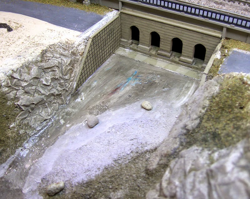
Where I wanted to simulate running water I brushed on the water effects product.  Using the brush and a bamboo skewer, I creating some wavy texture.  This was done where the streams were running down hill and also around the rocks.  This product also goes on white and looks terrible at first as shown in this photo but will dry clear.

Having seen this trick somewhere I had to try it. After the water effects product had dried, I applied small amounts of white paint to the ridges left by the water effects with the pointed end of a bamboo skewer to simulate white water. These are pointed out in this photo by blue arrows.

After adding one more coat of gloss medium, here is a looking down view of the completed river water with the bridges still removed.  I will still be adding some rocks and other details before re-installing the bridges.


Of the methods I've tried for modeling water I like this one the best, particularly for running water.  It's not the fastest but seems to offer the most control.

Thursday, August 14, 2014

Finishing the river scene

To display the Hot Springs Junction Ntrak module at the Hiller Avaiation Museum's Train's and Planes exhibit last April, I had laid temporarily tracks on the Ntrak lines.  To complete the scenery in the river these tracks and the three concrete bridges were removed to access the area under the tracks.  In this post I have divided the river into lower and upper scenes.

The lower river scene


With the suggestion and offer of materials from one of the members of Peninsula Ntrak, I chose to cover the area around the bridge abutments with boulders.

White glue was spread around the abutments and pilings, then the boulders were laid on top of that. Other smaller and more rounded rocks were placed throughout the river bed area.

Here is the view from above with almost all of the boulders in place.  The counter sunk screw holes on the ends of the bridges are for the flat head screws that hold the bridges in place.


The upper river scene


This river originates on the module from a concrete bridge that carries the upper railroad racks and station platforms over the river.

This was made by combining two sections from Green Max kit # 47-5.  The side retaining walls were scratch built from styrene tile.  All were air brushed Model Master aged concrete color and weathered.


There will be a vehicle bridge connecting the two roads seen in this photo that also came for Green Max kit # 47.5 - handy kit !  In this last photo it can been seen that some "water" is running out from under the bridge arches and down the river, more on that in the next post.

Friday, August 8, 2014

Finishing the station scene - Part 2

After spending what hobby time I had in July completing the wiring and controls for this module, this month I'm back to finishing the area around the station.  With the platforms now secured to the module, it was time to install the foot bridge.  Remember from the post Building the Green Max foot bridge that I had made my own support columns so that they would be long enough to reach ground level while the stairs would end at the platform level.

I cut short sections of square tubing that the bridge columns would fit right into.  These were painted concrete color before being placed into square holes cut into the foam.  White glue does not react with the foam and it was placed around the square tubing sections to settle into the space around the tubing.

Here is an over head view showing how the foot bridge rest on the platforms.   While the two pairs of columns on the outside were attached to the module as shown above, the center pair was attached directly to the surface with E6000 adhesive as that area is on wood.

The plate on the bumper at the end of the station spur track was painted white and a black "X" decal was applied over the white background.  In this photo, the empty concrete footings for the foot bridge can be seen in the foreground.  I had intended to attach the foot bridge to the module but it fits so nicely just sitting in the footings, I now plan to have it removable for better access clean the tracks.

A bit of weathering


For weathering I use Bragdon's weathering powders in several different colors.  I use a small shorted bristle paint brush to work the power into the spots I want it to be applied and the larger brush for smoothing.

Here's the assembled scene with both the station and the foot bridge weathered.  The foot bridge got a bit more than the station building as I recall most of them I have seen in rural areas have had a deferred maintenance look to them.


The station area is now basically complete.  Later I will be adding some signs, people, and other details but for now I am going to move on to completing the river scenes.

Thursday, July 31, 2014

Controls for a junction module - Part 2


The control panel is now complete and shown here  mounted on the front of the module.  There is also a place to mount in on the back of the module.  This is the first time I've used this method for control panels and really like the way it looks.


July is almost over and it seems the only model railroading work I did this month involved the electronics but it's something that had to get done and it's completion marks a big step in this module being ready for it's next show.

While many model railroaders hate working with the wiring and controls, I rather like it.  Besides this control panel, I also built a power supply to AsiaNrail specs and repaired another smaller power supply I use to power accessories on the modules including the turnout motors.  Next month (starting tomorrow), it's back to finishing more of the scenery.

Tuesday, July 29, 2014

Controls for a junction module - Part 1

The Musashi-Koyama module set has two tracks, and two pairs of cross over turnouts.  The only controls I have for those modules is a slide switch on the roof of one of the taller buildings, and a "mode" switch under each module.  The mode switch is only set once during setup and selects between a double track or single track arrangement.

While the Musashi-Koyama modules actually have more track and turnouts than the mountain division / AsiaNrail lines on the Hot Springs Junction module, the fact that it is a junction and because the module may used in either a combined Ntrak / AsiaNrail layout or an AsiaNrail only layout an actual control panel was going to be needed.  This control panel would have features for:

  • Control of cross over between AsiaNrail and Ntrak Mountain lines
  • 4 track blocks - AsiaNrail, Station Spur, Mountain Right, Mountain Left
  • Each block selects one of two throttles or center off.
  • Indicator lights would be nice but not absolutely necessary
  • Can be mounted on front or back of module depending on setup

I created this drawing on Visio.  This will be used as a drilling template and also as an overlay on the control panel.  The large dots are for mini toggle switches and the small dots are for LEDs.


During the operation of the layout a the Hiller Aviation Museum in April the Hot Springs Junction was used as one of three terminals.  Referring to the drawing above, a train would enter from the AsiaNrail layout and come into either the Station Spur or the Mountain Left, which was also a spur in this setup.  It was envisioned that it would have been useful if the Mountain Right block could also have been used as a storage track.  There is actually a similar track arrangement not far from my home at the Mountain View light rail station which is at the end of the line.

I picked up an aluminum box measuring 6.25 inches by 3.5 inches and 3 inches deep.  Using some scrap of 1/8 inch Plexiglas I made a panel that would fit on the top and drilled all the holes in it using the drawing as a template.  I also tried out the product shown next to the Plexiglas panel to clear up any scratches and found that it actually works.

This view is of the bottom of the control box. Mounting brackets were made from 1/2 inch aluminum angle.  The holes for the screws that will mount it to the module were made in such a way as to allow a screw drive to pass through the hole on the opposite side.  A pair of 8-32 Tee nuts are mounted on both the front and back of the module to mount the control box.