Showing posts with label Electronics. Show all posts

Saturday, March 1, 2025

The Tomix Pachinko building- Part 1

Years ago I found this Tomix building at a local train show for 10 dollars and when I built these modules I found it easy to fill in an empty space with it.  It already had some unpainted interior details so I thought some day I would like to finish this structure and light the inside.  That day has finally come.


Tomix buildings like these often come with a nice sidewalk section that interlocks with the structure base.  This set had this front sidewalk plus another section for a parking lot in the back.  When I first installed this on the module there was no room for the sidewalk so I left it off.  Now that the modules are developed further, I decided to use the sidewalk so I cut the parking lot section to fit and moved the structure back just a bit.


This building has a sign in the front that lights with 3 LED's connected to a circuit that makes them flash in sequence.  The light was barely visible through the sign and I had considered replacing it with something else.  What I discovered was that the LED's were positioned too far behind the sign for the light to be effective.  I found that if I fitted styrene tubing over the LED's the light was more focused so decided to keep the sign. 


I built a small 3 volt regulator circuit to replace the pair of AA batteries that had been powering the sign.  The load is very small but I still added a heat sink and did a 24 hour test to be sure this circuit would stay cool.


To light up the interior of the first floor I made a ceiling out of .030 styrene sheet and glued it to the existing plastic piece that holds the lighted sign and front doors and windows in place.  5 surface mount LED's were inserted through holes in the ceiling and scraps of decoder wires were used to connect them to a PC board from a Kato GP50.  This was also something left over from a decoder installation.  These will run on the 12 volt DC power circuit with a current limiting resistor.  The photo below shows the top side of this ceiling.


To be continued .......

Thursday, January 26, 2023

An automated point to point system

It's been a long time since I've posted here and a long time since there has been a chance to set up and run the AsiaNrail layout.  The last setup we had was at the Narrow Gauge Convention in Sacramento back in the fall of 2019.  During all this time with the pandemic my energy has been directed toward my American Prototype home layout.  But AsiaNrail now does have an exhibit scheduled for April, more on that in a future post.

Having something on the schedule has motivated me to get the modules out and get them ready.  There is one project that I have been thinking about for a long time and thought now would be the time.

The AsiaNrail layout always has several stub end branch lines and often there are not enough operators to have them running along with a continuous running loop.  I thought it would be great to have something that could automatically do a point to point run on one or two of the branch lines.  My experience with the Azatrax IR train detection products on my home layout lead to to try out their point to point controller. 

First step after I got the controller was to try it out on a temporary Unitrack setup.  The control circuit itself is the green circuit board to the left of the track.  I made some temporary holders for the IR sensors from wood scraps.  I had this running two different trains that would alternately go out from one of two spurs, go to the end of the single line and stop for about 10 seconds before returning.  The controller took care of the turnout and also has an adjustable momentum feature built into it. 

Being satisfied with the results of the test setup, I went about making this into a setup that could work on a modular layout.  The Hot Springs Junction module would be the base and would have the IR sensors permanently installed under the tracks next to the station platforms.  In this mode the detection is caused when the IR signal is reflected off the bottom of a train.  The sensors would be behind the platforms at the station so would be almost totally hidden when viewed from the side.  The overhead view below shows these sensors pointed out in green.


The sensors at the remote end will need to be on whatever module is at the end of the run.  I made up a fixture from brass to hold the sensors at the end of a 25 foot long cable.  In this photo it is shown in it's storage box along with other layout electrical hardware.


The controller board was mounted in a plastic box with a clear lid so the indicator LED's could be seen.  This will hang on the leg cross brace under the module.  In this photo the lid has not been installed yet.  Connections to this control box are for power, the remote sensor and the main cable connection to the module.


This small test layout using the Hot Springs Junction module and the two small single track modules was used to further test and experiment with this control system.  Because the turnouts on the Hot Springs Junction module were not wired as power routing, I was not able to make make this setup work the same way as the Unitrack test setup.  In the interest of having something ready for this next show, for now this is going to run just the one train point to point.  Later, when I have more time I will redesign and wire things to use the full function of the controller. 


Saturday, March 25, 2017

The great module re-wiring of 2017

The operating concept for the Musashi-Koyama module set was to have it function either as a double or single track module, be in line with other modules that are either double or single track, or be an end of line terminal.  When connected to a single track modules, it could be used as a passing siding.  Cross overs and power routing was controlled by a single switch on the roof of one of the taller buildings.   There was a mode switch under the modules which bridged the inputs to the two tracks together when running in the single track mode.


The drawing above is a very basic representation of the tracks and controls how they were originally set up.  While it had preformed quite well several times as a terminal end module, the first time we attempted to use it in line between other modules did not work out so well.  I had not considered that while the main line might be single track, the second track may extend to an adjoining module and that power may be routed by a turnout on that module.  Another issue was that in this type of setup there was no way to control the cross overs independently.


Here is another drawing showing the basic representation of how the track circuits on the module are now controlled.  Each crossover now has it's own control.  Also one rail on each track was isolated and their connections are made through another pair of switches so either track next to the station platform can be turned off.

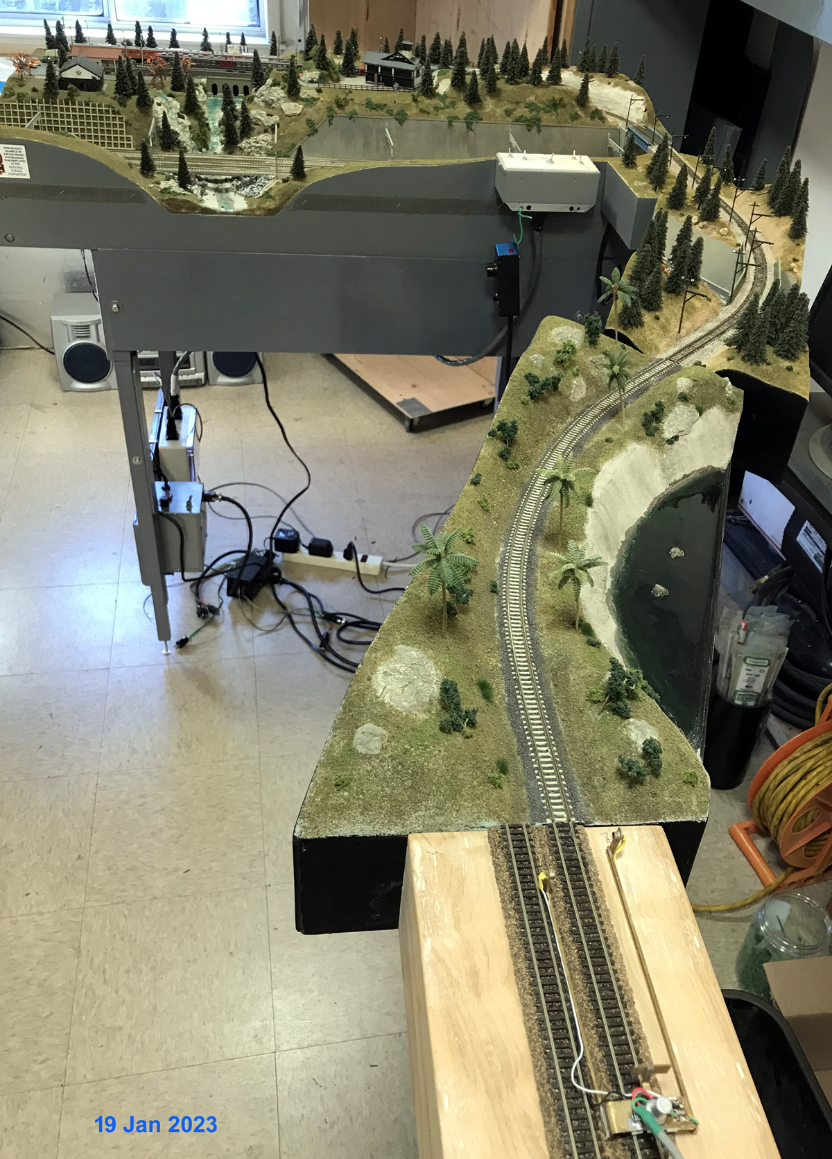
This photo shows the new gaps cut in the rails at one end of the platform.  Most of our trains have electrical pickup in all units meaning a train needs to stop within the platform track limits to avoid bridging the gap.  I installed some black post to make these limits more visible to operators.

The 4 new toggle switches are located on the roof of the same building as the original single switch was.  This paper building has a rigid structure under it to support the switches and also houses 2 tortoise motors.
This is what an operator standing behind the sky board inside the layout will see looking down at the roof of the building.   The empty square hole was where the original switch was.

I use 16 pin AMP connectors to make the all connections between the modules.  I had two pairs of wires left unused so I used one pair to carry the switched platform track over to the other module.

The mode switches used to select single or double track modes was no longer needed and was removed.  In it's place I installed RCA jacks which are the AsiaNrail standard connection for turnout power.  I don't use this power so these will just carry it thru the module using the last spare pair of wires on the 16 pin AMP connector.

Another modification made was to create a switchable isolation gap somewhere within the module per AsiaNrail standards.

The best place to do this was at the gap between the middle and small module as rails already have a gap there and I only needed to place some switches in the connection between the modules.


I have been testing the heck out of this and all seems good at this point so it's now on to more scenery.

Thursday, July 31, 2014

Controls for a junction module - Part 2


The control panel is now complete and shown here  mounted on the front of the module.  There is also a place to mount in on the back of the module.  This is the first time I've used this method for control panels and really like the way it looks.


July is almost over and it seems the only model railroading work I did this month involved the electronics but it's something that had to get done and it's completion marks a big step in this module being ready for it's next show.

While many model railroaders hate working with the wiring and controls, I rather like it.  Besides this control panel, I also built a power supply to AsiaNrail specs and repaired another smaller power supply I use to power accessories on the modules including the turnout motors.  Next month (starting tomorrow), it's back to finishing more of the scenery.

Tuesday, July 29, 2014

Controls for a junction module - Part 1

The Musashi-Koyama module set has two tracks, and two pairs of cross over turnouts.  The only controls I have for those modules is a slide switch on the roof of one of the taller buildings, and a "mode" switch under each module.  The mode switch is only set once during setup and selects between a double track or single track arrangement.

While the Musashi-Koyama modules actually have more track and turnouts than the mountain division / AsiaNrail lines on the Hot Springs Junction module, the fact that it is a junction and because the module may used in either a combined Ntrak / AsiaNrail layout or an AsiaNrail only layout an actual control panel was going to be needed.  This control panel would have features for:

  • Control of cross over between AsiaNrail and Ntrak Mountain lines
  • 4 track blocks - AsiaNrail, Station Spur, Mountain Right, Mountain Left
  • Each block selects one of two throttles or center off.
  • Indicator lights would be nice but not absolutely necessary
  • Can be mounted on front or back of module depending on setup

I created this drawing on Visio.  This will be used as a drilling template and also as an overlay on the control panel.  The large dots are for mini toggle switches and the small dots are for LEDs.


During the operation of the layout a the Hiller Aviation Museum in April the Hot Springs Junction was used as one of three terminals.  Referring to the drawing above, a train would enter from the AsiaNrail layout and come into either the Station Spur or the Mountain Left, which was also a spur in this setup.  It was envisioned that it would have been useful if the Mountain Right block could also have been used as a storage track.  There is actually a similar track arrangement not far from my home at the Mountain View light rail station which is at the end of the line.

I picked up an aluminum box measuring 6.25 inches by 3.5 inches and 3 inches deep.  Using some scrap of 1/8 inch Plexiglas I made a panel that would fit on the top and drilled all the holes in it using the drawing as a template.  I also tried out the product shown next to the Plexiglas panel to clear up any scratches and found that it actually works.

This view is of the bottom of the control box. Mounting brackets were made from 1/2 inch aluminum angle.  The holes for the screws that will mount it to the module were made in such a way as to allow a screw drive to pass through the hole on the opposite side.  A pair of 8-32 Tee nuts are mounted on both the front and back of the module to mount the control box.